An electrostatic brake uses high voltage to create a strong force, allowing very low power control over an applied force. This has a lot of potential uses, and I’m interested in exploring how it can be applied further.

For example, commercial haptic gloves use a variety of methods to provide force feedback, but most are bulky, heavy, and expensive. Electrostatic clutches could provide a lightweight, low-cost, and much smaller alternative, but are more difficult to control.
What is an electrostatic brake?
Electrostatic clutches rely on the electrostatic force that exists between two charged plates. By applying a high voltage across these plates, we can control a very strong attractive force very quickly.
The general formula for the electrostatic force between two parallel plates is:
Where:
- = force (N)
- = relative permittivity of dielectric
- (vacuum permittivity)
- = plate overlap area ()
- = applied voltage (V)
- = dielectric thickness (m)
Choices Choices Choices…
Based on this formula, I had to make several design choices about the target voltage, the dielectric, and the plate geometry.
Firstly, I looked at the plates themselves. I want this design to work with as little space as possible, so I decided to assume the plates would be , or .
Next, I looked at options for the dielectric. Because distance is squared in the formula, I wanted to keep the dielectric as thin as possible. However, I also needed a dielectric that could withstand high voltages without breaking down. In addition, increasing the dielectric constant will boost the force, so I want a material with a high .
After looking at many options, I ended up going with a 10 µm thick Mylar film, with:
- Very high dielectric breakdown voltage (~ 500 V/µm)
- Very thin (10 µm readily available)
Using the overlap area of and , the resulting force is:
At :
At :
In practice, only about half of this can be realized as usable friction force, since not all compressive force translates directly into shear resistance. Regardless, these forces indicate that the project is definitely feasible.
Voltage Generation
The primary challenge in designing an electrostatic clutch is supplying the high voltages needed. Most existing solutions are either bulky, or very expensive, neither of which are good for my project.
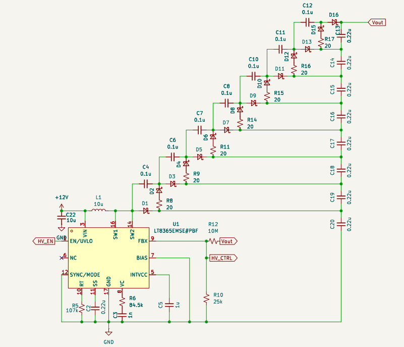
While looking for methods to generate these high voltages, I came across the LT8365 boost converter IC, whose datasheet included a reference design for generating 420V.
It did this by using a two charge pumps attached to the output of the converter, allowing the voltage at the switch to remain at just 140V, while outputting much higher levels.
Since each stage increases the output by the voltage at the switch, I decided to include 8 charge pump stages, keeping the voltage on the IC slightly lower, at 125V for an increased safety margin, as shown below.

How to control it?
The next challenge is how to actually drive the clutch plates. Controlling this very high voltage can be difficult, and this difficulty is compounded by the fact that electrostatic clutches require a bipolar drive signal to function properly.
This is because simply applying a DC voltage can lead to charge injection in the dielectric, which causes the brake to turn off much slower than otherwise possible. I found that most sources generally suggests 10-20Hz as a good switching speed to optimize for power consumption and quick release.
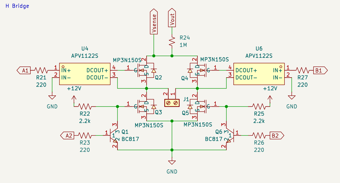
To create this 10Hz bipolar square wave, I used an H-bridge circuit with high voltage mosfets to alternate the high-voltage potential across the plates.
How to control that?
I designed the H-bridge, but because the voltages involved are so high, I could only find N channel mosfets. N-channel mosfets are generally better than P-channel, but are meant to be used for low-side switching, as they require a gate voltage higher than the source voltage to turn on.
This means that if I want to use them, I need to use over 1000 volts as a control signal if I want to control the high side switches. Obviously a normal microcontroller wouldn’t work for this, and I didn’t want a whole second high voltage supply just for switching.
The solution to this took a lot of research, but eventually I stumbled across the APV1121S.
This IC is a optoelectric gate driver, and it works by having a small LED inside the package and a series of photovoltaic cells across from it. This allows it to generate a fully isolated ~10v, which means I can simply attach it to the 1000V supply, and get 1010V on the other side when I trigger the LED.
With this all in mind, my final H-bridge design looks like this:

Controlling more things!
Because this design was intended for initial experimentation, I wanted to be able to control the output voltage digitally. This would allow me to easily test different voltages and see how they affected the clutch performance.
I also wanted to experiment with variable voltages to provided different levels of force feedback. To do this, I used the LTC7106, a current DAC that could produce very small currents ( to ), which could then be injected into the boost converter feedback loop to control the output. It also includes a digital output that can be used to entirely turn of the HV boost stage.
Additionally, I included a voltage divider on the HV output to measure the voltage, combined with a unity gain op-amp that would reduce the load on the drive circuit. This will also come in handy for some other uses, as will be explained later.
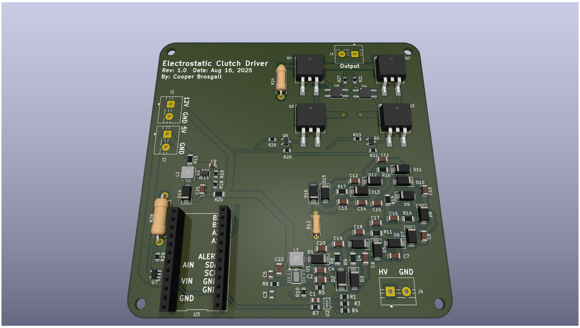
This all connects to a microcontroller, which can then be programmed to adjust the output voltage and frequency as needed.
